Servo Programmer – DPC-20 Setup Guide
1. Instruction for CAN Series Servo using DPC-20
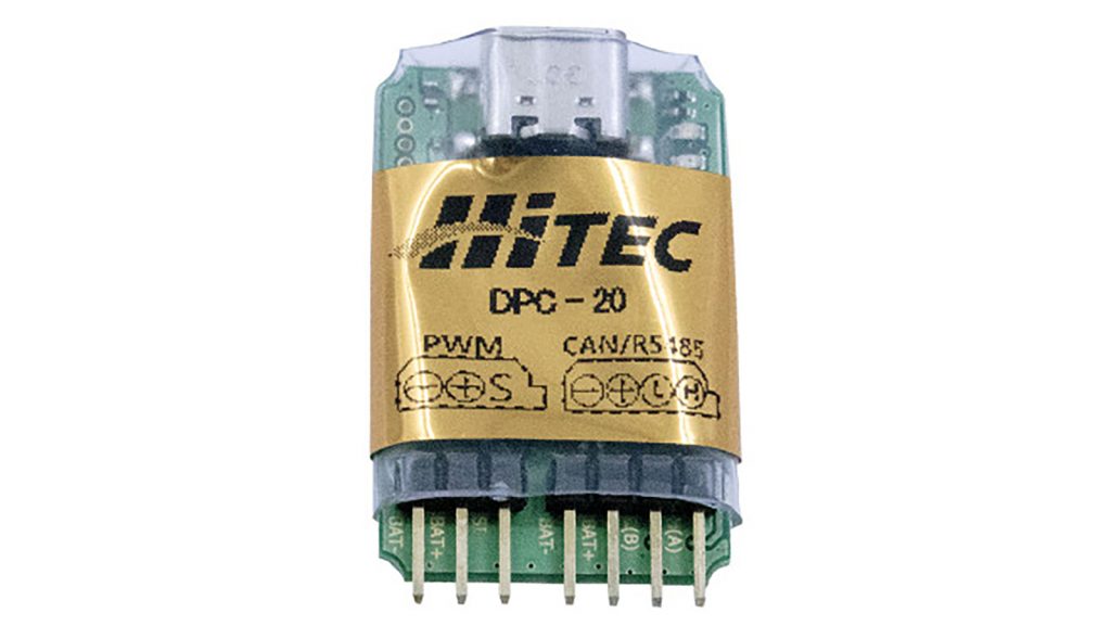
HiTEC’s DPC-20 is a modern servo programming and configuration interface designed for digital servo actuators. It connects HiTEC servos to a USB-C enabled, internet-accessible device and allows configuration via a web-based user interface.
The DPC-20 allows users to adjust and test all standard servo parameters, including End Points, Direction, Speed, Fail-Safe, Dead Band, Soft Start, and Overload Protection. It also supports Data Save/Load and Program Reset functions, all accessible through a user-friendly interface.
Important Information:
- Hardware Type: PC USB-C to 4-pin (CAN) interface
- Capable of configuring and testing HiTEC digital servo actuators
- Different servo actuator series require dedicated UI programs due to variations in communication protocols
- Ensure to connect the appropriate power supply to the DPC-20 for the connected servo actuator
- DPC-20 Wiring Diagrams are located on the DPC-20 UI HUB DOCUMENTATION.
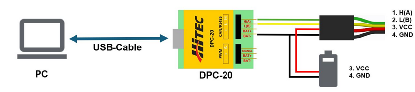
For any voltage exceeding 18V or current exceeding 3A, use the direct connection method to prevent damage or malfunction.
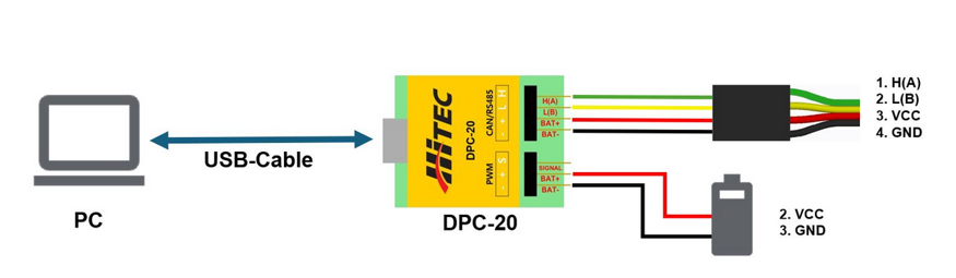
There are two ways to connect the DPC-20 to the servo: via the DPC or using a direct connection.
Connection via DPC-20:
Connection directly:
Please download the HiTEC DPC UI Hub Software:
http://support.HiTECrcd.net:7700/files/install_dpc_HiTEC.exe
You will also need the CP2102 driver, which can be downloaded from the Silicon Labs website:
https://www.silabs.com/software-and-tools/usb-to-uart-bridge-vcp-drivers?tab=downloads
Please install both software tools before proceeding.
Open the HiTEC DPC UI Hub Software and connect the DPC to the PC.
A start screen will appear and check for updates. Once the update check is complete, click Run.
The Software Hub Screen is displayed:
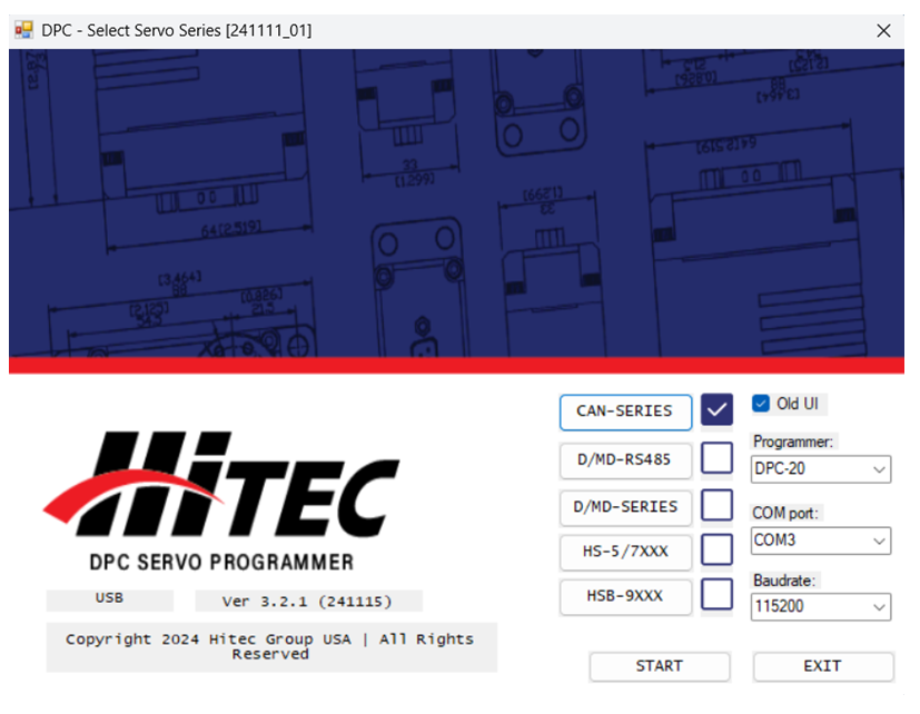
On the right side, select “DPC-20” as Programmer, use the associated COM Port and set the Baudrate to ‘115200‘. Then click START.
‘Old UI‘ Checkbox:
If the “Old UI” checkbox is activated, the HiTEC CAN Config Tool will start. Otherwise the AIO UI will launch.
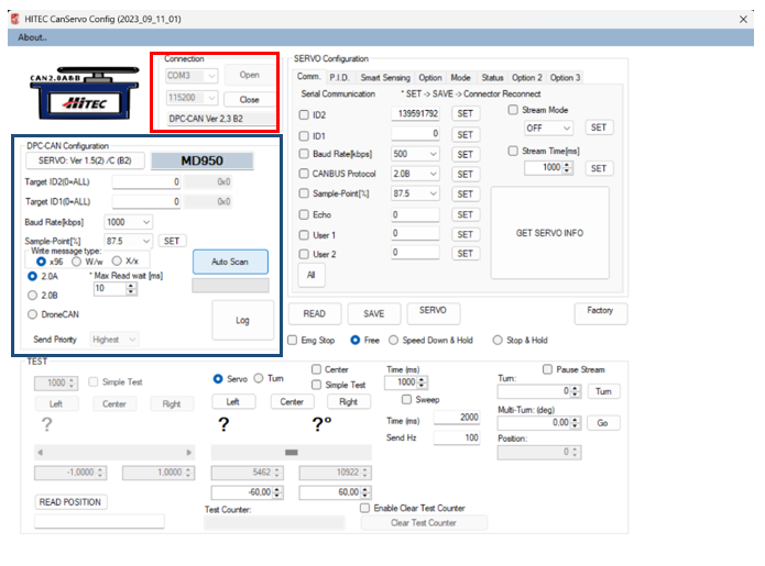
(RED) Select the required COM Port and set the Baudrate to 115200.
(BLUE) Configure the CAN bus communication settings. The default CAN settings for the servos are:
Baudrate: 1000kbps
Protocol: 2.0A
If the CAN bus communication settings are unknown, click Auto Scan to allow the software to detect the correct settings automatically.
Click Read Servo Version to display the firmware information. If a servo version is displayed, the servo is connected correctly.
How to Program the Servo
To set the desired servo parameters, enter the values in the corresponding fields. Some fields are dropdown menus and allow only predefined settings to be selected. After changing the parameters, click the SET button next to it. This step must be performed for each changed value.
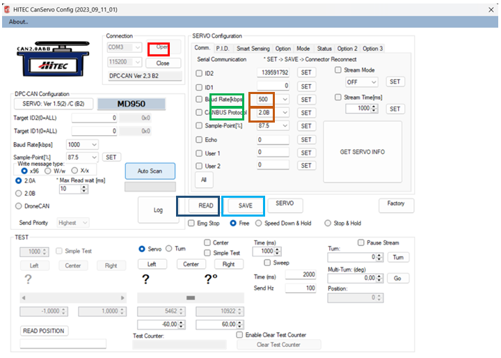
Example: Changing the Baudrate and protocol:
- Open the ‘Comm.’ Tab (RED).
- Select the desired Baudrate and protocol from the dropdown menu (GREEN).
- Click SET (DARK RED) and SAVE (BLUE).
- Reconnect the servo or press SERVO to apply the changes (LIGHT BLUE).
If the Baudrate or protocol has been changed, the settings under “DPC-CAN Configuration” must be updated to the same values.
Select the correct COM port, set the Baudrate to ‘115200’ and press Open (RED).
The PC is now connected to the DPC.
Under Protocol, set the Baudrate of the servo, select the protocol in use and click Scan (BLUE). If one or both values aren’t available, the servo will be detected automatically using the scan function.
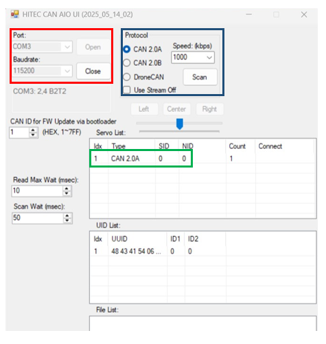
A servo will appear below ‘Servo List’. Double-click on it (GREEN) to open the parameter view.
If only a few parameters are displayed and some marked with question marks, please click Refresh. A list of all parameters should then be displayed.
How to Program the Servo
Example to change the Baudrate:
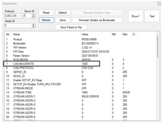
Double click CAN/BAUDRATE (GRAY) to open the setting window.
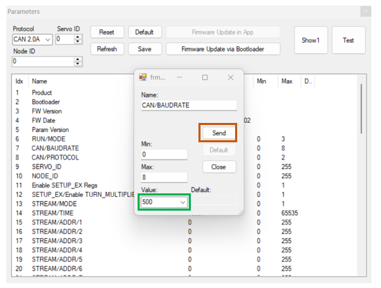
Use the Dropdown menu to change the value for Baudrate (GREEN) and click Send (RED).
To save the changed Baudrate permanently to the servo, click Save □. Reconnect the Servo.
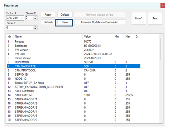
To change other parameters of the servo, the steps are identical. Some parameters will have a numerical input instead of a Dropdown menu and the values are limited to the Min/Max range.
All accessible registers and the message format can be found in the HiTEC CAN Manual: